5.3
The View Menu
 |
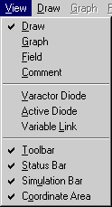
The View menu
is shown in Figure 1-3. It is subdivided into
three sections. The first section of the View
menu allows you to select one of the four working
modes: Draw, Graph, Field, and Comment.
A check mark appears in front of the selected item.
At the same time, the corresponding menu becomes
en-abled in the main menu bar.
|
| Figure 1-3: The
View Menu. |
| Draw |
The Draw menu
allows you to draw and edit the structure to be modeled.
The TLM grid is displayed when Draw is active. |
| Graph |
The Graph menu
allows you to graph and visualize all input and output
functions of the Simulator. These are source waveforms,
time and frequency domain responses of the probes, and
Scattering parameters. It also allows setting the
attributes of the graph display and of the ports. |
| Field |
The Field menu
allows displaying and visualizing all electromagnetic
field components and the dissipated power distribution in
all or part of the structure. Both 2D and 3D
visualization is available. Display attributes can be set
for both types of display. |
| Comment |
This item opens a
comment box that accepts plain text; it will be stored in
the tlm file, together with all the other data.
Copying, cutting and pasting of text are possible by
means of the Ctrl+C, Ctrl+X and Ctrl+V keystrokes,
respectively. |
Tip: |
Clicking the right
mouse button brings up a menu that contains
the three first items Draw, Graph
and Field. Using this menu may be
faster. |
The second section of the View
menu allows you to inspect and edit the parameters of three types
of elements: Varactor Diode, Active Diode, and Variable
Link. A check mark appears in front of the active item. Only
one type can be implemented in a given structure, but several
elements of the same type having identical parameters may be
used.
| Varactor Diode |
This item is enabled
if a varactor model has been created previously under the
Draw menu. Click on Varactor Diode to bring
up a dialog box displaying the parameters set during that
implementation. You may edit the values in each field and
enter the new parameters by clicking OK or hit the
<Enter> key. |
| Active Diode |
This item is enabled
if an active diode model (such as a Gunn or Tunnel diode)
has been created previously under the Draw menu.
Click on Active Diode to bring up a dialog box
displaying the parameters set during that implementation.
You may edit the values in each field and enter the new
parameters by clicking OK or hit the <Enter>
key. |
| Variable Link |
This item is enabled
if a variable link (a model for implementing and
programming a moving electric wall) has been created
previously under the Draw menu. Click on Variable
Link to bring up a dialog box displaying the
parameters set during that implementation. You may edit
the values in each field and enter the new parameters by
clicking OK or hit the <Enter> key. |
Note: |
When the Draw option
is active, the right mouse button menu contains the items
Varactor Diode, Active Diode and Variable Link
as well. However, these are used for drawing rather than
viewing or editing such elements and duplicate the items
with the same name in the Draw menu (see
below). |
The third section of the View
menu allows you to show or hide the Toolbar, Status Bar,
Simulation Bar, and Coordinate Area.
