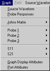
| Source Waveform |
Source Waveform displays
the source function selected under the Source Waveform
menu. |
| Probe
Responses |
Probe Responses displays
simultaneously the time domain and frequency domain
responses at all probes (up to three). |
| Johns Matrix |
Johns Matrix displays
the Johns Matrices (impulse responses) assigned to
dispersive Johns Walls in the structure. |
| Probe 1 |
Probe 1 displays
the time domain response V(t) or the
frequency response V(f) (spectrum)
at Probe 1 in Magnitude or Phase. |
| Probe 2 |
Probe 2 displays
the time domain response V(t) or the
frequency response V(f) (spectrum)
at Probe 2 in Magnitude or Phase. |
| Probe 3 |
Probe 3 displays
the time domain response V(t) or the
frequency response V(f) (spectrum)
at Probe 3 in Magnitude or Phase. |
| S11 |
S11 displays
the Magnitude or Phase of the complex
reflection coefficient S11 at the Input Port. |
| S21 |
S21 displays
the Magnitude or Phase of the complex
transmission coefficient from the Input Port to the
Output Port. Note To compute
Scattering parameters, you must generate a reference
signal identical to the incident wave at the Input Port.
A reference structure must therefore be implemented that
has the same geometry and excitation as the Input Port,
and the probes must be in the same position with respect
to the source. The S-parameters are computed as
follows:
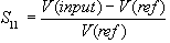 , ,
where the voltages are the Fourier transforms of the
impulse responses at the probes assigned to the Input and
Reference Ports.
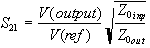 , ,
where the voltages are the Fourier transforms of the
impulse responses picked up at the probes assigned to the
Output and Reference ports, and the impedances are the
reference impedances (characteristic impedances) of the
Input and Output; Ports. Reference and Input Ports must
have identical geometry, impedance, mode of propagation,
and excitation.
|
| Graph Display
Attributes |
Graph title,
name, and scale of the axes can be edited in the dialog
box. During a simulation, the scale of the axes adjusts
dynamically to the signal, but the user can change the
graph display attributes once the simulation is stopped.
The display can be smooth or discretized (Bar Graph off
or on). S-parameters can be displayed in dB or in
absolute values. |
| Port
Attributes |
Any of the three
probes (Probe 1 to 3) can be assigned to the reference,
input or output port. To verify the number of a probe,
proceed as follows:
- In the View menu,
select Draw,
- In the Draw Menu, select Select
Element,
- Point to a probe and click the
left mouse button,
- Read the number of the probe
in the status bar.
Input and reference ports must
always have the same width, mode and characteristic
impedance. However, the output port can have a different
geometry, impedance and/or propagation mode. TEM or TE_10
modes may be selected. The width of the ports must be
specified as well. The relative dielectric constant
selected by the program is that of the Computation Region
in which the probe is located. In the special case where
all ports have the same characteristics, the port widths
and modes selected are immaterial as long as they are the
same for the input and output port.
| Warning |
In the case of TE10
mode propagation in either the input or the
output port, or both, S21 should be
computed only at frequencies above the
highest dominant cutoff frequency in the
structure since singularities at cutoff
frequencies can cause unreliable numerical
results. |
|