5.9 The Simulation Control Menu

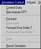
With the Simulation Control menu you control the simulation process. 

Figure 1-9: The Simulation Control Menu.
Control Data Control Data allows you to set the simulation control data in the Control Data dialog box. It contains four data field groups.

In the Time Domain Data field group, specify the following:

  • Total number of time steps - This integer determines the number of time steps after which the simulation will stop. It is also called the number of iterations. This number is always counted from time zero. If you increase this number after a simulation and then start the computation again, the simulation will simply continue until the new Total number of time steps has been reached. A counter displays the time step in the Status Bar during the simulation. 
  • Time steps between updates - This integer determines the update interval for all graphs, field plots, and for the Discrete Fourier Transform (DFT). A low number (1 to 5) is preferable for dynamic field display, while a higher number (> 20) is more appropriate for visualizing the evolution of frequency domain data such as S-parameters. 

In the Frequency Domain Data field group, specify the following:

  • Number of frequency points - This integer determines the number of frequencies at which the Fourier transform will be computed. They are spaced linearly.
  • Lower frequency (GHz) - The lower frequency limit of the Fourier transform window.
  • Upper frequency (GHz) - The upper frequency limit of the Fourier transform window.

In the TLM Mesh Data field group, specify the following :

  • Cell size Delta_L in [mm] - The value of the mesh parameter can be entered and modified, even after a structure has been entered. It thus allows you to scale a structure geometry and all its time and frequency domain characteristics. 

The following values are computed automatically by the simulator.

  • Time Step Delta T in [ps] is based on the velocity of impulses on the link lines. . This time step cannot be changed by the user since it is "hard-wired" in TLM.
  • In the TEM Dispersion Error in Percent field group, the maximum dispersion error in the discrete TLM mesh is displayed for the value in the Upper frequency (GHz) window. In practice, the dispersion error may be much lower than indicated there.
  • Error in attenuation constant - displays the upper bound for the dispersion error in the attenuation constant of a TEM wave. This error is zero if all dielectric subregions are lossless. If different subregions have different conductivity, the maximum error in the lossiest subregion is displayed.
  • Error in phase constant - displays the upper bound for the dispersion error in the phase constant of a TEM wave. If different subregions have different permittivity, the maximum error in the subregion with the highest permittivity is displayed.
Recompute DFT Recompute DFT allows you to compute the Discrete Fourier Transform again without repeating the field simulation. Since the impulse response at probes is stored in memory, the Fourier Transform can be recomputed again and again. The dialog box is the same as that of the control data window. Simply change the numbers in the active fields (Time steps between updates, frequency domain data, and the mesh parameter Dl. This feature is particularly useful for expanding or contracting the width and resolution of the Fourier window. It also allows you to study the effect of dimensional tolerances on the frequency characteristics.
Forward Compute forward in time. Equivalent to Plus Plus.gif (850 bytes) in the Simulation Bar. If the program is ready to start, Forward is enabled, and you can activate this command with the left mouse button. The simulation process can be stopped at any time by clicking on Stop.
Backward Compute backward in time. Equivalent to Minus Minus.gif (816 bytes) in the Simulation Bar. If the program has previously performed a simulation forward in time, you can activate this command with the left mouse button, and the program computes backward in time to where it started. The reverse simulation process can also be stopped at any time by clicking on Stop.
Forward One DeltaT Compute one step forward in time. Equivalent to Plus.gif (820 bytes) in the Simulation Bar. If the program is ready to start and the maximum number of time steps allowed by the simulator has not yet been reached, this command is enabled, and you can activate this command with the left mouse button. 
Backward One DeltaT Compute one step backward in time. Equivalent to Minus.gif (794 bytes) in the Simulation Bar. If the program is ready to start, this command is enabled, and you can activate it command with the left mouse button.

Note Backward-in-time simulation is enabled if and only if the mesh does not have 

  • Johns Matrix boundaries
  • Nonlinear subregions (Diodes).
  • Probes

In the reverse mode, the simulation will be computed backward to timestep zero, unless you stop it. Note that during reverse simulation the sources are ignored. No energy is extracted from the mesh at the source points. 

In a true backward simulation process, a lossy boundary or material would become active and re-inject the energy absorbed during the forward cycle. Since this would create numerical instability, all lossy walls and computation regions remain lossy during time reversal. However, if you model a lossless structure, the backward simulation will be realistic.

Stop Stop the simulation.  It is equivalent to Stop.gif (824 bytes) in the Simulation Bar.
Reset Simulator Clicking on Reset Simulator resets the simulator to its initial state at t=0 (except the alpha-value for the Variable Link) and clears all simulation results from the RAM of the computer. You must reset the simulator before you can edit the structure of the source waveform. Only the Animation Region and its Sampling Mode can be changed without resetting. Reset Simulator is equivalent toReset.gif (820 bytes) in the Simulation Bar.

Note You will not be able to change any element of the structure (except the Animation Region) once you have started a simulation and generated some output data. To make any changes you must first reset the simulator. This will enable most commands. Then start a new simulation. Previous simulation results can be stored using the Save or Save As command in the File menu.